
Resonant RLC series circuits and formulas of the resonant frequency , the cutoff frequencies are developed, the bandwidth and the quality factor are defined and all are used in examples with detailed solutions.
In what follows, the upper case letter \( I \) is the complex (polar) form of the real current \( i \) and the upper case letter \( V_i \) is the complex (polar) form of the real voltage \( v_i \).
A resonant series RLC circuit calculator may be used to verify the calculations of the examples below and also for more practice and investigations of these circuits.
Consider the series RLC circuit shown below.
For a circuit supplied by a voltage source of frequency \( f \), the total impedance \( Z \) of the series RLC circuitis given by:
\[ Z = R + j \left(\omega L - \dfrac{1}{\omega C} \right) \]
The relationship between the current \( I \) and the voltage \( V_i \) is given by
\[ I = \dfrac{V_i}{Z} \]
where \( V_i \) and \( I \) are the complex form of the voltage \( v_i \) and the current \( i \) respectively.
Using the definition of the magnitude of a complex number, the magnitude \( |Z| \) is given by
\[ |Z| = \sqrt {R^2 + \left(\omega L - \dfrac{1}{\omega C} \right)^2} \]
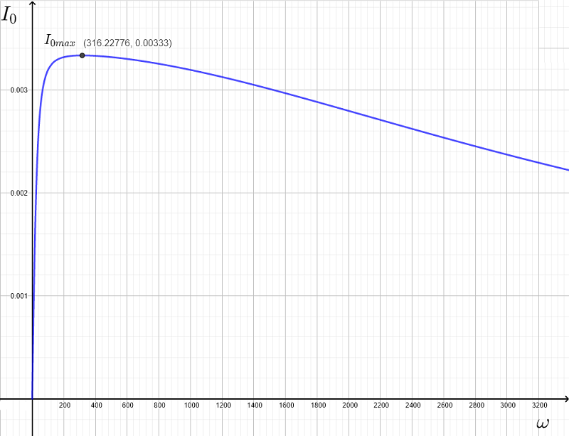
If \( V_0 \) is the peak value of the voltage source \( v_i = V_0 \cos (\omega t) \), then the peak value \( I_0 \) of \( I \) is given by
\[ I_0 = \dfrac{V_0}{ |Z| } = \dfrac{V_0}{ \sqrt {R^2 + \left(\omega L - \dfrac{1}{\omega C} \right)^2} } \]
The frequency of resonance is defined as the frequency for which \( I_0 \) is maximum or when the magnitude of \( Z \) is minimum.
Since the resistance \( R \) is independent of the frequency, the minimum value of \( |Z| \) occurs at \( \omega = \omega_r \) such that
\[ \left(\omega_r L - \dfrac{1}{\omega_r C} \right) = 0 \]
Solve the above for \( \omega_r \) to obtain the resonant frequency
\[ \omega_r = \dfrac{1}{\sqrt {L C}} \quad \quad (I) \]
At the resonant frequency \( \omega = \omega_r \), we have:
\[ \color{red}{ Z = R } \]
For \( V_0 \), the peak value of the voltage source \( v_i \), the peak value \( I_0 \) of \( I \) is given by
\[ \color{red} { I_0 = \dfrac{V_0} {R} } \]
Let \( X_L = \omega L \) and \( X_C = \dfrac{1}{\omega C} \)
\[ \color{red} { X_L = X_C } \]
Example 1
Let \( R=300 \; \Omega \), \( L = 100 \; mH \) and \( C = 100 \mu F \) in the series RLC circuit above.
a) Find the resonant frequency \( \omega_r \)
b) Graph \( |Z| \), \( X_L = \omega L \), \( X_C = \dfrac{1}{\omega C} \) and \( I_0 \) as a function of the frequency \( \omega \) and discuss the graphs obtained.
Solution to Example 1
a)
The resonant frequency \( \omega_r \) is given by
\[ \omega_r = \dfrac{1}{\sqrt {L C}} = \dfrac{1}{\sqrt{100\times10^{-3} \times 100 \times 10^{-6}}} \approx 316.23 \]
b)
Below are shown the graphs of \( |Z| \), \( X_L \) and \( X_C \).
From the graphs, \( |Z| \) has a minimum value equal to \( R = 300 \; \Omega \) (point A)
The graphs of \( X_L \) and \( X_C \) intersect (point B) and are therefore \( X_L = X_C \) or \( \left(\omega_r L - \dfrac{1}{\omega_r C} \right) = 0 \) .

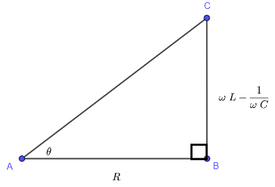
The average power \( P_a \) delivered to the series RLC circuit is given by: \[ \displaystyle \quad \quad P_a = \dfrac{V_0^2}{2 |Z|} \cos \theta \quad \quad (II) \] where \( \theta \) is the argument of the impedance \( Z = R + j \left(\omega L - \dfrac{1}{\omega C} \right) \) and is given by \[ \theta = \arctan \left( \dfrac{ \omega L - \dfrac{1}{\omega C} }{R} \right) \] Using inverse trigonometric functions properties, we have \[ \tan \theta = \left( \dfrac{ \omega L - \dfrac{1}{\omega C} }{R} \right) \] \( \theta \) may be assumed to be an acute angle of a right triangle as shown below. (Use the definition of the tangent of an angle in a right triangle and see that you can get \( \tan \theta \) as defined above.
We now define the cutoff frequencies as the frequencies \( \omega_c \) at which the power \( P_a(\omega) \) in (III) is half the maximum power \( P_{a max} \) in (IV).
Hence we need to solve the equation
\[ P_a (\omega_c ) = \dfrac{1}{2} \left(\dfrac{V_0^2}{2 \; R} \right) \]
\[ \dfrac{V_0^2 R}{2 \left({R^2 + \left(\omega_c L - \dfrac{1}{\omega_c C} \right)^2} \right) } = \dfrac{1}{2} \dfrac{V_0^2}{2 \; R} \]
Simplify to
\[ \dfrac{ R}{2 \left({R^2 + \left(\omega_c L - \dfrac{1}{\omega_c C} \right)^2} \right) } = \dfrac{1}{4 R} \]
Cross multiply, simply and rewrite the above equation as
\[ (\omega_c L - \dfrac {1}{\omega_c C } ) = R^2 \]
Solve by extracting the square root to obtain two equations
\[ \omega_c L - \dfrac {1}{\omega_c C} = \pm R \]
Multiply all terms by \( \omega_c C \) and simplify
\[ \omega_c^2 L C - 1 = \pm \omega_c R C \]
Rewrite as quadratic equations in standard forms
\[ \omega_c^2 L C \pm \omega_c R C - 1 = 0\]
Solve the first quadratic equation \( \quad \omega_c^2 L C + \omega_c R C - 1 = 0\) to obtain two solutions
\[ \omega_{c1} = \dfrac {- R C \pm \sqrt{ (R C)^2 + 4 L C }}{ 2 L C } \]
Solve the second quadratic equation \( \quad \omega_c^2 L C - \omega_c R C - 1=0\) to obtain two solutions
\[ \omega_{c2} = \dfrac {R C \pm \sqrt{ (R C)^2 + 4 L C}}{ 2 L C } \]
We have a total of 4 solutions. Note that the quantity \( \sqrt{ (R C)^2 + 4 L C } \) is larger that \( RC \) and therefore only two solutions are valid since the cutoff frequency is a positive quantity. The cutoff frequencies \( \omega_{c1} \) and \( \omega_{c2} \) are the two solutions given
\[ \omega_{c1} = \dfrac {- R C + \sqrt{ (R C)^2 + 4 L C }}{ 2 L C } \]
\[ \omega_{c2} = \dfrac {R C + \sqrt{ (R C)^2 + 4 L C}}{ 2 L C } \]
We already found the the resonant frequency \( \omega_r = \dfrac{1}{\sqrt{LC}} \). Use simple algebra to rewrite \( \omega_{c1} \) and \( \omega_{c1} \) in terms of \( \omega_r \)
\[ \omega_{c1} = - \dfrac{R}{2 L} + \sqrt{ \left(\dfrac{R}{2 L}\right)^2 + \omega_r^2} \quad \quad (V) \]
\[ \omega_{c2} = \dfrac{R}{2 L} + \sqrt{ \left(\dfrac{R}{2 L}\right)^2 + \omega_r^2} \quad \quad (VI) \]
Note that
\[ \omega_{c1} \times \omega_{c2} = \omega_r^2 \quad \quad (VII) \]
The bandwidth of the resonant circuit is defined by: \( \Delta \omega = \omega_{c2} - \omega_{c1} \)
The quality factor \( Q \) is defined by \[ Q = \dfrac{\omega_r}{\Delta \omega} \] Substitute \[ Q = \dfrac {\omega_r} { \left(\dfrac{R}{2 L} + \sqrt{ \left(\dfrac{R}{2 L}\right)^2 + \omega_r^2} - \left(-\dfrac{R}{2 L} + \sqrt{ \left(\dfrac{R}{2 L}\right)^2 + \omega_r^2} \right) \right)} \] Simplify \[ Q = \omega_r \dfrac{L}{R} \quad \quad (VIII) \]
Example 2
a) Find the resonant frequency, the cutoff frequencies and the quality factor \( Q \) for a series RLC circuit with \( R=300 \; \Omega \), \( L = 100 \; mH \) and \( C = 100 \; \mu F \).
b) Graph the average power \( P_a \) against the common logarithm of the angular frequency \( \omega \) and check graphically the resonant and cutoff frequencies found analytically in part a) above.
Solution to Example 2
b)
Given
\[ L = 100 \; mH = 100 \times 10^{-3} \; H = 0.1 \; H \; , \quad \; C = 100 \; \mu F = 100 \times 10^{-6} \; F = 0.0001 \; F\]
Resonant frequency: \( \omega_r = \dfrac{1}{\sqrt{L C}} = \dfrac{1}{\sqrt{0.00001}} = 316.22776 \approx 316.23 \)
\[ \omega_r^2 = \dfrac{1}{L C} = \dfrac{1}{0.00001} = 100000 \]
\[ \dfrac{R}{L} = \dfrac{300}{0.1} = 3000 \]
Using the formulas (V) and (VI) above, we obtain the two cutoff frequencies and the quality factor as follows:
\[ \omega_{c1} = - 1500 + \sqrt{ 1500^2 + 100000} \approx 32.97 \text{ rad/s} \]
\[ \omega_{c2} = 1500 + \sqrt{ 1500^2 + 100000} \approx 3032.97 \text{ rad/s} \]
The quality factor \( Q \) is given by
\[ Q = \dfrac{316.23}{3032.97 - 32.97} \approx 0.1054 \]
b)
Below is shown the graph of \( P_a \) against \( Log_{10} (\omega) \) so that the plot shows some useful symmetries. From the graph, the maximum power is equal to \( 0.001666 \) Watts and occurs at \( Log_{}(\omega_r) = 2.5\). Hence
\[ \omega_r = 10^{2.5} \approx 316.22776 \text{ rad/s} \]
The half maximum power line (in red) is given by \( y = \dfrac{1}{2} \) of the maximum of \( P_a = \dfrac{}{} = 0.00083\) and intersect the graph at the cutoff frequencies such that
\[ Log_{10}(\omega_{c_1}) = 1.51481 \; \text{which gives} \; \omega_{c_1} = 10^{1.51481} = 32.71975 \text{ rad/s} \]
\[ Log_{10}(\omega_{c_2}) = 3.48356 \; \text{which gives} \; \omega_{c_2} = 10^{3.48356} = 3044.80861 \text{ rad/s} \]
Hence the graph gives values of the resonant and cutoff frequencies that are close to those found analytically in part a).

Example 3
A series RLC resonant circuit is to designed so that its has the frequencies \( f_{c_1} = 650 \) Hertz and \( f_{c_2} = 950 \) Hertz as lower and upper cutoff frequencies.
a) Calculate the capacitance of the capacitor \( C \) and the inductance of the inductor \( L \) if the resistance of the resistor \( R \) is equal to \( 30 \Omega \).
b) What is the quality factor of the circuit?
Solution to Example 3
a)
Calculate the angular frequencies.
\[ \omega_{c_1} = 2 \pi f_{c_1} = 1300 \pi \text{ rad/s} \]
\[ \omega_{c_2} = 2 \pi f_{c_1} = 1900 \pi \text{ rad/s} \]
Use the formula (VII) developed above
\[ \omega_{c_1} \times \omega_{c_2} = \omega_{r}^2 \]
to calculate he resonant frequency \( \omega_{r} \) of the circuit.
\[ \omega_{r} = \sqrt {\omega_{c_1} \times \omega_{c_2}} = \sqrt {1300 \pi \times 1900 \pi } = 100 \sqrt{247} \pi = 4937.400 \text{ rad/s} \]
\[ \omega_{c_2} - \omega_{c_1} = \dfrac{R}{L} \]
Hence
\[ L = \dfrac{R } {\omega_{c_2} - \omega_{c_1}} = \dfrac{30} {1900 \pi - 1300 \pi } = 0.01591 \text{H} \]
\[ \omega_{r} = \dfrac{1}{\sqrt {L C} } \]
\[ C = \dfrac{1}{\omega_{r}^2 L} = \dfrac{1}{(100 \sqrt{247} \pi)^2 \times 0.01591} = 2.5783 \times 10^{-6} \text{F} \]
b)
The quality factor is given by
\[ Q = \dfrac{\omega_{r}}{\omega_{c_2} - \omega_{c_1}} = \dfrac{100 \sqrt{247} \pi}{1900 \pi - 1300 \pi } = 2.62\]