
It is here discussed how complex impedances are used to analyze currents and voltages in series RLC circuits. Complex numbers greatly simplifies the computations of impedances, currents and voltages in AC circuits.
Because the symbol \( i \) is used for currents in AC circuits, here we use \( j \) as the imaginary unit defined by \( j^2 = -1 \) or \( j = \sqrt{-1} \)
Lower case letters for current and voltages are used for real quantities. Upper case letters for current and voltages are used for complex quantities in polar form.
For a circuit supplied by a voltage source of frequency \( f \), the impedances of the different RLC components are given by:
The impedances in complex form \( Z_R \) of a resistance of resistance \( R \) is given by
\[ Z_R = R \]
The impedances in complex form \( Z_L \) of a inductor of inductance \( L \), also called inductive reactance, is given by
\[ Z_L = j \omega L \]
The impedances in complex form \( Z_C \) of a capacitor of capacitance \( C \) , also called capacitive reactance, is given by
\[ Z_C = - \dfrac{1}{\omega C} j \]
where \( \omega = 2 \pi f \)
The most important thing to note is that the inductive and capacitive reactances depends on the frequency of the voltage source.
Let \( V_i \), \( I \), \( V_R \), \( V_L \) and \( V_C \) be the complex form of \( v_i \), \( i \), \( v_R \), \( v_L \) and \( v_C \) respectively.
Apply Kirchhoff's law of voltage extended to complex impedances to write
\[ V_i - V_R - V_L - V_C = 0 \quad (1) \]
Apply Ohm's law extended to complex impedances to write
\[ V_R = Z_R I \]
\[ V_L = Z_L I \]
\[ V_C = Z_C I \]
Substitute the above in equation (1) to obtain
\[ V_i = Z_R I + Z_L I + Z_C I = 0 \]
Solve the above for \( I \)
\[ I = \dfrac{V_i}{Z_R + Z_L + Z_C } \]
Let \( Z \) be the equivalent complex impedance of the series RLC circuit defined as
\[ Z = Z_R + Z_L + Z_C = R + j \left(\omega L - \dfrac{1}{\omega C} \right) \]
The modulus of \( Z \): \[ |Z| = \sqrt{R^2 + \left(\omega L - \dfrac{1}{\omega C}\right)^2} \]
The argument of \( Z \): \[ \theta = arctan \left( \dfrac {\omega L - \dfrac{1}{\omega C}}{R} \right) \]
Note that both the modulus and the argument of impedance \( Z \) depend on the frequency (\( \omega = 2 \pi f \)) of the source voltage. This property is useful in the design of filters and has many other applications in electronic circuits.
Write \( Z \) in polar form
\[ Z = |Z| \; \angle \; \theta \]
The expressions for \( Z_R, Z_L, Z_C \) and \( Z \), done above, could be interpreted geometrically using phasors as shown below.

Let \( v_i = V_0 cos ( \omega t) \) , \( V_0 \) the peak of the source voltage
Euler formula of complex numbers
\[ e^{j \omega t} = \cos (\omega t) + j \sin (\omega t )\]
Hence \( v_i \) may also be written as
\[ v_i \; \text{is equal to the real part of} \; e^{j \omega t} \]
We now drop the "Real part of" and do all calculations in complex numbers and define \( V_i \) in complex form as
\[ V_i = V_0 e^{j \omega t} \]
and deduce \( I \) in complex form
\[ I = \frac{V_0 e^{j\omega t}}{|Z| \; \angle \; \theta} \]
and \( I \) in polar form is given by
\[ I = \dfrac{V_0}{|Z|} \; \angle \; \omega t - \theta \]
\[ I = I_0 \; \angle \; \omega t - \theta \quad \text{and} \quad I_0 = \dfrac{V_0}{|Z|} \]
Rewrite the impedances \( Z_R, Z_L\) and \( Z_C \) in polar form
\[ Z_R = R = R \; \angle \; 0 \]
\[ Z_L = j \omega L = \omega L \; \angle \; \pi/2\]
\[ Z_C = - \dfrac{1}{\omega C} j = \dfrac{1}{\omega C} \; \angle \; - \pi/2\ \]
The voltages are given by
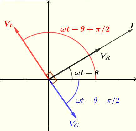
\[ V_R = Z_R I = (R \; \angle \; 0) (I_0 \; \angle \; {\omega t - \theta}) = R I_0 \angle \; \omega t - \theta \]
\[ V_L = Z_L I = (\omega L \; \angle \; \pi/2) (I_0 \; \angle \; {j\omega t - \theta}) = \omega L I_0 \; \angle \; {\omega t - \theta + \pi/2} \]
\[ V_C = Z_C I = (\dfrac{1}{\omega C} \; \angle \; - \pi/2) (I_0 \; \angle \; {j\omega t - \theta}) = \dfrac{I_0}{\omega C} \; \angle \; {\omega t - \theta - \pi/2} \]
The current \( I \) and voltages \( V_R \) , \( V_C \) and \( V_C \) are shown below using phasors.
Example 1
In a series RLC circuit, the source voltage is given by \( v_i = 20 \cos (\omega t) \), where \( \omega = 1000 \; rad/s \), the capacitance of the capacitor \( C = 200 \; \mu F \), the inductance of the inductor \( L = 400 \; mH\) and the resistance of the resistor \( R = 400 \; \Omega \).
a) Find the impedances of the capacitor, inductor and resistor and the impedance \( Z \) equivalent to the RLC circuit in complex form.
b) Find the current and all voltages in complex forms
c) Find the real current and voltages.
a)
The impedances in complex form \( Z_R \) of a resistance of resistance \( R \) is given by
\[ Z_R = R = 400 \; \Omega \]
The impedances in complex form \( Z_L \) of a inductor of inductance \( L \), also called inductive reactance, is given by
\[ Z_L = j \omega L = j \cdot 1000 \cdot 400 \cdot 10^{-3} = 400 j \; \Omega \]
The impedances in complex form \( Z_C \) of a capacitor of capacitance \( C \) , also called capacitive reactance, is given by
\[ Z_C = - \dfrac{1}{\omega C} j = - \dfrac{1}{1000 \cdot 200 \cdot 10^-6} j = - 5 j \; \Omega \]
\[ Z = Z_R + Z_L + Z_C = 400 + 400 j - 5 j = 400 + 395 j \]
b)
\[ v_i = 20 cos ( \omega t) \; \text{ hence the polar form of the source voltage is}: \; V_i = 20 \; \angle \; 0\]
We have seen above that the current in polar form is given by
\[ I = \dfrac{V_i}{Z_R + Z_L + Z_C } \]
Substitute the known quantities
\[ I = \dfrac{20 \; \angle \; 0}{400 + 395 j}\]
Rewrite the denominator in polar form
\[ 400 + 395 j = \sqrt {400^2+395^2} \; \angle \; \arctan\left(\dfrac{395}{400}\right) = 562.16 \; \angle \; 44.64^{\circ} \]
Evaluate \( I \)
\[ I = \dfrac{20 \; \angle \; 0}{562.16 \; \angle \; 44.64^{\circ}} = \dfrac{20}{562.16} \; \angle \; 0 - 44.64^{\circ} \]
Simplify
\[ I = 0.0356 \; \; \angle \; - 44.64^{\circ} \; \text{A} \]
\[ V_R = R I = 400 (0.0356 \; \; \angle \; - 44.64^{\circ}) = 14.24 \; V \; \angle \; - 44.64^{\circ} \; \text{V} \]
\[ V_L = Z_L I = 400 j (0.0356 \; \; \angle \; - 44.64^{\circ}) = 14.24 \; V \; \angle \; 45.36^{\circ} \; \text{V} \]
\[ V_C = Z_C I = - 5 j (0.0356 \; \; \angle \; - 44.64^{\circ}) = 0.18 \; V \; \angle \; -134.6^{\circ} \; \text{V} \]
Example 2
In a series RLC circuit the source voltage is given by \( v_i = 10 \cos (\omega t) \), the capacitance of the capacitor \( C = 200 \; \mu F \), the inductance of the inductor \( L = 200 \; mH\) and the resistance of the resistor \( R = 500 \; \Omega \).
a) Find the angular frequency \( \omega \) for which the imaginary part of the impedance \( Z \) is equal to zero.
b) Find the current and the voltages for the frequency found in part a).
a)
For a series RLC circuit, the impedance is: \[ Z = R + j(\omega L - \dfrac{1}{\omega C} ) \]
The imaginary part of \( Z \) is equal to zero gives:
\[ \omega L - \dfrac{1}{\omega C} = 0 \]
Solve for \( \omega \)
\[ \omega^2 L C = 1 \]
\[ \omega = \dfrac{1}{\sqrt{L C}} \]
Substitute \( L \) and \( C \) by their numerical values
\[ \omega = \dfrac{1}{ \sqrt{ 200\cdot10^{-3} \cdot 200 \cdot 10^{-6}}} = 158.11 \; \text{ rad/s} \]
b)
\[ I = \dfrac{V_i}{Z} = \dfrac{10 \; \angle \; 0}{R \; \angle \; 0} = \dfrac{10}{500} \; \angle \; 0 = 0.02 \; \angle\; 0 \]
\[ V_R = R I = 500 \cdot 0.02 \; \angle \; 0 = 10 \; \angle\; 0 \]
\[
\begin{split}
& \\
V_C = Z_C I = \dfrac{1}{\omega C} \; \angle \; -90^{\circ} \cdot 0.02 \; \angle\; 0 \\
& = \dfrac{1}{\omega C} \cdot 0.02 \; \angle \; -90^{\circ} \\
& = \dfrac{1}{158.11 \cdot 200 \cdot 10^{-6}} \cdot 0.02 \; \angle \; -90^{\circ} = 0.6324 \; \angle \; -90^{\circ}
\end{split}
\]
\[
\begin{split}
& \\
V_L = Z_L I = \omega L \; \angle \; 90^{\circ} \cdot 0.02 \; \angle\; 0 \\
&= \omega L \cdot 0.02 \; \angle \; 90^{\circ} \\
&= 158.11 \cdot 200 10^{-3} \cdot 0.02 \; \angle \; 90^{\circ} = 0.6324 \; \angle \; 90^{\circ}
\end{split}
\]
Example 3
In a series RLC circuit the source voltage is given by \( v_i = V_0 \cos (2 \pi f t) \), where \( f \) is the frequency, the capacitance of the capacitor \( C = 47 \; \mu F \), the inductance of the inductor \( L = 100 \; mH\) and the resistance of the resistor \( R = 200 \; \Omega \).
a) Find the total impedance \( Z \) equivalent to the capacitor, the inductor and the resistor in series in terms of the frequency \( f \) and write it in polar form \( Z = |Z| \; \angle \; \theta \)
b) Find the frequency \( f \) such that \( \theta = -60^{\circ} \).
Solution to Example 3
a)
For a series RLC circuit, the impedance is: \[ Z = R + j(\omega L - \dfrac{1}{\omega C}) \]
Substitute the known quantities by their numerical values
\[ Z = R + j(\omega L - \dfrac{1}{\omega C}) = 200 + j( \omega \cdot 100 \cdot 10^{-3} - \dfrac{1}{\omega \cdot 47 \cdot 10^{-6}})\]
\[ Z = \sqrt {200^2 + ( \omega \cdot 100 \cdot 10^{-3} - \dfrac{1}{\omega \cdot 47 \cdot 10^{-6}})^2} \; \angle \; \arctan \left(\dfrac{\omega \cdot 100 \cdot 10^{-3} - \dfrac{1}{\omega \cdot 47 \cdot 10^{-6}}}{200}\right) \]
b)
\[ \arctan \left(\dfrac{\omega \cdot 100 \cdot 10^{-3} - \dfrac{1}{\omega \cdot 47 \cdot 10^{-6}}}{200}\right) = -60^{\circ} \]
\[ \dfrac{\omega \cdot 100 \cdot 10^{-3} - \dfrac{1}{\omega \cdot 47 \cdot 10^{-6}}}{200} = \tan (-60^{\circ}) = -1.73205 \]
Multiply all terms of the equation by \( 200 \) to eliminate the denominator
\[ \omega \cdot 100 \cdot 10^{-3} - \dfrac{1}{\omega \cdot 47 \cdot 10^{-6}} = -346.41 \]
Multiply all terms of the equation by \( \omega \cdot 47 \cdot 10^{-6} \) to eliminate the denominator
\[ 47 \cdot 10^{-7} \omega^2 - 1 = -0.01628127 \omega \]
Solve the above quadratic equation for \( \omega \) and select the positive solution.
\[ \omega = 53.23 \; \text{ rad/s} \]
\[ \omega = 2 \pi f = 60.3682 \]
\( f = \dfrac{60.3682}{2 \pi} = 9.60789 \text{Hz} \)
Example 4
In a series RLC circuit the source voltage is given by \( v_i = V_0 \cos (2 \pi f t) \), the capacitance of the capacitor \( C = 470 \mu \)F, the inductance of the inductor \( L = 50 \)mH and the resistance of the resistor is \( R \).
a) Find the total impedance \( Z \) equivalent to the capacitor, the inductor and the resistor in series in terms of the frequency \( f \) and write it in polar form \( Z = |Z| \; \angle \; \theta \)
b) Find the resistance \( R \) and the frequency \( f \) such that \( \theta = 40^{\circ} \) and \( |Z| = 100 \).
a)
For a series RLC circuit, the impedance is: \[ Z = R + j(\omega L - \dfrac{1}{\omega C}) \]
Write \( Z \) in polar form
\[ Z = \sqrt{R^2 + (\omega L - \dfrac{1}{\omega C})^2} \; \angle \; \arctan \left( \dfrac{\omega L - \dfrac{1}{\omega C}}{R} \right) \]
b)
\[ \theta = \arctan \left( \dfrac{\omega L - \dfrac{1}{\omega C}}{R} \right) = 40^{\circ} \]
\[ \dfrac{\omega L - \dfrac{1}{\omega C}}{R} = \tan 40^{\circ} = 0.83909\]
\[ \omega L - \dfrac{1}{\omega C} = 0.83909 \text{R} \]
Substitute the above in \( |Z| \)
\[ \sqrt{R^2 + (0.83909 R)^2} = 100 \]
Solve for \( R \)
\[ R = 76.6048 \; \Omega \]
\[ \omega L - \dfrac{1}{\omega C} = 0.83909 R = 64.27832 \]
Solve for \( \omega \)
\[ \omega = 1317.8557 \text{rad/s} \]
\[ f = \dfrac{1317.8557}{2\pi} = 209.74324 \text{Hz} \]